")
")
")
")

")
")

Vademecum Heat Pumps


1. What is a heat pump and how does it work

The heat pump is a machine able to transfer heat from one environment at lower temperature to another at higher temperature. The machine consists of a closed circuit in which a refrigerant gas (freon) circulates, in order to carry out this function. Depending on the temperature and pressure conditions in which it is located, it can be in the liquid or vapor state.
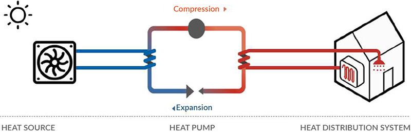
By means of the latent heat of evaporation and condensation and the action of the compressor, this gas allows on one side of the circuit to absorb heat (evaporation), and transfer it by raising the temperature using the compressor and transfer it (condensation) to the other side of the circuit although it is at a higher temperature. With this transfer of energy from lower temperature to higher temperature, the heat pump is able to multiply the electrical energy entered into the system resulting in a performance coefficient (COP) higher than 1. Thanks to its high COP, this technology is therefore the ideal solution for a compromise between the energy costs, energy consumption and environmental sustainability.
Depending on the configuration of the machine, it is possible to invert the heat pump’s thermal cycle by reversing the direction of transfer, therefore taking heat from the warm source and then transferring it to the cold one. In this case, what used to be the evaporator now becomes the condenser, and the other way around.
2. Available technologies
Depending on the physical state of the energy source used, it is possible to identify two families of heat pumps; of these, the Air-Water heat pumps are always the easiest to install because they do not require any complex installation.
2.1
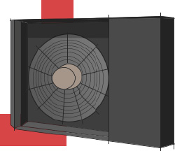
Air-water heat pumps
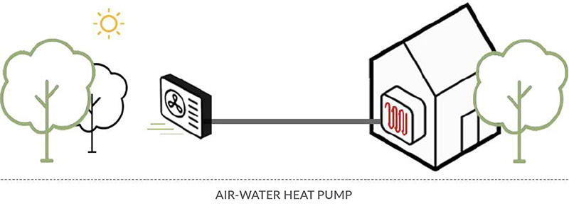
This heat pump type uses the outside air as energy source. The heat is absorbed by the outside air by means of a finned pipe heat exchanger and a fan in order to be transferred to the water in the heating circuit. It is easy to imagine that the energy absorption power of the heat pump depends on the outside climatic conditions and that its efficiency will be lower the colder the climatic conditions are. This type of Heat Pump is available in different configurations in terms of both the system (Monoblock, split, with integrated storage), and the performance (standard, for harsh climate, for High temperature water). Depending on the climate in which the machine has to work and on the temperature required for proper operation of the heating system, it is possible to choose between three different versions of the machine, which differ in the type of the compressor, the relative mapping of the operating cycle and also the refrigerant gas used. In terms of system, the most commonly used machine configuration is the split one, because it is equipped with a hydronic module that can be wall-mounted inside the dwelling, thus minimizing the need of the external installation. In terms of operation, in addition to standard machines operating up to 55°C, on the market there are machines that have been specifically designed to operate in harsh climates while maintaining a high output power to the heating circuit, as well as machines designed for high tempera
2.2
Water-water heat pumps
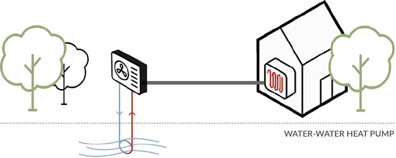
This type of heat pump uses as energy source water that can come either from aquifers or wells or from other heat exchange circuits such as geothermal probes. Since heat is always present underground also during winter, thanks to the geothermal probe that can reach substantial depths, it is possible to capture this heat with a circuit and then transfer it to the water of the heating circuit. Since the water has a more stable temperature throughout the year, its presence ensures the maintenance of excellent performance in any season. On the other hand, this type of heat pump always requires an accurate hydrogeological analysis before feasibility and profitability can be defined. In addition, in protected areas of landscape constraints it may also be necessary to request specific authorizations.
3. Choose the most suitable machine

The choice of the most suitable machine for your needs requires three evaluations: the type, the configuration and lastly the size.
3.1
The type
In order to choose the type of Heat Pump that can suit your needs, you have to first of all consider the temperature at which it has to work, that is the flow temperature required by the system terminals of the heating circuit. On the market there are machines operating at low or high temperature. The choice can be made according to the following scheme:
3.1.1 Standard machines
They are appropriate for new installations and for low energy consumption dwellings and are able to produce hot water up to 55°C reaching high COP values. Although they are able to produce heat with outside air temperatures down to -20°C, in case of harsh project temperatures it is recommended to check their performance, as below 2°C these machines suffer a decrease in performance, both in terms of COP and real supplied power.
3.1.2 Harsh Climate machines
They are suitable to operate in a very cold environment. The ideal choice to ensure that the heating capacity be maintained even at very low temperatures. This range of heat pumps is able to produce heat with external air temperatures down to -28°C keeping constantly the real delivered power up to an external temperature of -20°C without the aid of an electric super heater.
3.1.3 High Temperature machines
They are appropriate for the replacement of the boiler in dwellings with high temperature radiators, allowing to maintain unchanged the distribution and the system terminals. This type of machine is able to produce hot water up to 65°C reaching high COP values and operating with external air temperatures down to -15°C.
4. Sizing
The sizing of a heat pump to use in replacement of an existing boiler shows two major critical issues, the cost of the investment and the electrical power required by these machines. For these two reasons, it is necessary to make a correct sizing that allows you to choose the most suitable dimension for your needs, avoiding the most common error, oversizing. The task of the heat pump is to reintegrate the thermal energy dispersed by the dwelling in order to keep its internal temperature constant. You should always ask for an advice and consult a specialist for a complete project before proceeding with the purchase and installation of a heat pump. Below are two methods that will help you calculate the most suitable machine size for your needs. The first method is stricter but requires precise data for the calculation, while the second is more approximate and therefore needs oversizing that is essential in order not to undersize the machine.
4.1
Calculation of the nominal heat output of the heat pump – Proper method
There are different methods to calculate the nominal heat output required for the heat pump depending on the available data. The most reliable method is the one that starts from the annual heat energy requirement for winter comfort needs. In order to make the calculation, you need to have the data listed below:
(ETH) Annual Thermal Energy Requirement for Winter Comfort, that is the thermal energy required during the heating season for winter comfort.
-
(S) The Useful Surface that is the net floor area of the heated rooms of the dwelling excluding the partitions and external walls and including door thresholds and spaces underneath the installation terminals. The data is available in the design of the dwelling.
-
(GG) The Day Degrees, that is the sum of the positive differences between the conventionally set indoor temperature at 20°C and the outdoor temperature during a winter heating period, determined according to the climatic zone of the location.
-
(TEST) The External Design Temperature is the minimum external temperature at which the heat generator provides sufficient heat energy to ensure that the internal temperature stay stationary.
-
(H) The Daily Hours of Operation or the maximum daily operating hours of the heating system. In addition, in this case you can refer to the standard.
Una volta in possesso di tutti questi dati sarà possibile effettuare il calcolo della potenza termica nominale della Pompa di Calore utilizzando la seguente formula:
4.2
Calculation of the nominal heat output of the heat pump – Approximate method
If you don’t have access to any energetic certification, it is possible to calculate the Annual Thermal Energy Requirement for Winter Comfort (ETH) based on the consumption data indicated in the traditional gas bill. If you want to use the bill, however, the advice is to add up the consumption of several consecutive years in order to have a more truthful average consumption so that an average in different climatic conditions is considered. Once the annual consumption expressed in cubic meters has been established, it is possible to calculate the ETH with the following formula:
Where:
 is the gas consumption in cubic meters
-
 is the power obtained per cm of gas (10.5 kWh for natural gas and 12.8 kWh for LPG)
 -
 is the boiler efficiency (0.82 open chamber / 0.86 sealed chamber / 0.97 condensing)
 -
 is the number of users per DHW consumption
 -
 is the annual energy consumption per capita for the production of DHW expressed in kWh
 -
 is the useful surface, that is the net floor area of the heated rooms in the dwelling
Once the value of the Annual Thermal Energy Requirement for Winter Comfort (ETH) has been calculated, it will be possible to consider the relationship for the calculation of the nominal thermal power indicated in the method previously described. It should be noted that the calculation indicated is overestimated (by approximately 10%) as it does not take into account any free heating from solar radiation on glass surfaces.
Note: : If the fuel used is LPG, it is standardly purchased in LITERS and not in M3, so it is good to know that 1 M3 of LPG is equivalent to 4 litres.
4.3
The size
- Once established the nominal heat output that the heat pump will be able to deliver, it will be possible to select the correct machine taking into account the following parameters within the performance schemes provided by the manufacturer of the Heat Pump of your interest.
External Design Temperature (A)
-
The flow temperature to the heating circuit (W)
The installation technician usually calculates the value of the flow temperature to the heating circuit during the project development phase. Normally a floor heating installation requires a flow temperature around 35°C; a fan-convector or fan-radiator heating can require from 35°C to 50°C depending on the operating conditions, while a radiator always requires 65°C to be able to trigger the convective motion of air. You can find below the performance scheme in relation to the external temperature and flow temperature of the machines of the Sintesi series.
4.4
The configuration
The Heat Pumps are normally produced with different configurations in order to satisfy all plant installation requirement. Most manufacturers provide three different configurations for almost all Heat Pump models: the monoblock, the split and the tower also called “All in one”.
The MONOBLOCK is the easiest and the most compact configuration to install, as the word says it is a single unit and has to be installed outside the dwelling. Being a single unit, it does not require connections in the gas circuit, which is already complete and tested by the manufacturer, making the installation easier. The disadvantage is that the connections of the hot water supply and return pipes must be made outside the dwelling. It is necessary to track these pipes with heating cables so as to avoid icing when the system is not operating; heating cables that reduce de facto the performance of the machine as they add to the electrical consumption of the building.
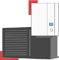
The SPLIT is the most common configuration among those available because it has a compressor to be installed outside the dwelling and a hydronic module to be installed inside. The internal hydronic module contains the condensing part of the Freon and the hot water supply; therefore, it is noiseless being without a compressor. The reduced dimensions allow the installation in the spaces previously occupied by the boiler. In this case, however, the installer will have to make the flow and return connections of the cooling circuit between the indoor and outdoor units
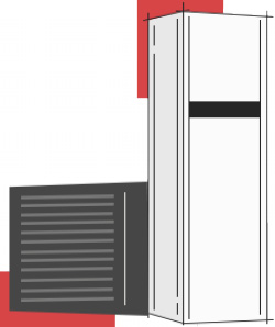
The COMPLETE is the most elegant configuration among those available, because it has a compressor installed outside the house and a hydronic module installed inside with a built-in inertial tank and a domestic hot water tank. The built-in tanks in the unit allow for an optimization of installation time and a reduction of probability of error. Also in this case, the installer will have to make the supply and return connections of the cooling circuit between the indoor and outdoor units.
4.5
DHW production
Both standard heat pumps and heat pumps for harsh climate are designed to work with refrigerant as the R410 or R32. Therefore, since they are able to produce hot water up to 55°C they can be used also for the production of Domestic Hot Water but due to the temperature below 60°C, they are not able to carry out the thermal disinfection cycles necessary to avoid the formation of bacteria (legionella). Therefore, the advice is to use them only for heating and/or cooling in the case of a reversible machine, leaving the production of DHW to a more specific independent unit such as a heat pump water heater, which uses the R134a refrigerant and is therefore able to carry out these disinfection cycles. If you have a high temperature water production machine operating with R407C refrigerant or a specific machine for heating and DHW production using a second compression stage with R134a, then it is possible and convenient to keep all the heat production within the same unit.
Note: it is recommended to install thermostatic mixing valves according to the regulations in force.
5. Installation

5.1
The inertial storage tank
Although the heat pump is a modulating machine, it is always recommended to insert a heat load compensation tank into the circuit for the following reasons:
It ensures best operating conditions of the heat pump by optimizing the “stop & go” cycles and, consequently, lowering its consumption.
-
It allows the connection of several heating circuits.
-
It allows the hydraulic disconnection between the heat pump and the system so that the two circuits can operate with more suitable flow rate and temperature differential. Usually the heat pumps operate with delta T=5°C while, depending on the system terminals, the distribution circuit could operate with even higher delta T’s.
It is possible to avoid the installation of the thermal storage tank in case there is only one direct circuit with radiant panels with high storage capacity and almost constant flow rate. If the machine is equipped with a scroll compressor (On/Off), the inertial storage tank is mandatory. The typical size of the storage tank is 20 liters per kWh of thermal power supplied by the machine.
5.2
Expansion vessel
The expansion vessel is a “container” that is connected to the hot water system and is used to support the change in volume given by heating/cooling of the water inside the system. This allows to eliminate potential issues such as the breakage of storage tanks and/or distribution pipes.
To properly size an expansion vessel you need to know the liters of water circulating within the system. For example, if our system contains 100 liters of water, and knowing that the specific volume difference between water at 5 C° and at 90 C° is 0.03590 l/ Kg (1,0359-1,000), our expansion vessel will need to have a volume of 0,03590 x 100 = 3,59 liters. Below you will find a table with the multiplier to be used in relation to the cold and hot temperature differential.
5.3
Advices for external machine installation
The machine should be installed outdoors and can be exposed to rain. Provide for expansion vessels both on the circuit of the system and on the circuit of the tank if any, with automatic vents on the highest points of the circuits. Install safety valves depending on the operating pressure considering that the machine cannot exceed 5.5 bar on the hydronic circuit side. You should also provide for a water loading system in the circuit with pressure reducer and built-in pressure gauge. To guarantee the efficiency of the plate heat exchangers over time, it is advisable to provide for a Y filter capable of blocking any impurities in a position that is easily accessible. To facilitate maintenance, add connections and the possibility of disconnecting the hydraulic circuit in order to wash the exchanger by reversing the flow. On the system side, it is necessary to size the circuit with the installation of a hydraulic compensator if it is not able to guarantee the project water flow rate. The heat pump must be installed on a stable surface, for example a basement or concrete floor.
5.4
Checking the installation location
Before positioning the machine, you must check the place of installation and operation. If possible, place the pump in a covered area (e.g. under a shelter, roof, etc.). The exposure of the unit to unfavorable climatic conditions results in reduced efficiency. The air heat pump cannot be used in closed spaces without air ventilation. In the case of indoor units, this problem can be solved by using special air ducts. You must ensure there is a free space around the unit (see minimum dimensions in the following diagram):
5.5
Precautions for connecting the refrigerant gas circuit
The maximum distance of the gas line between the Indoor and Outdoor Unit is 10 linear meters with a maximum height difference of 4 meters. In all cases different from the above, it is necessary to redefine the quantity of gas and design the refrigeration line.
5.6
Typical installation flow charts
Below are the typical installation flow charts of a Heat Pump for Heating, Heating and Cooling and for Heating and DHW production. Clearly, the flow chart is a “Concept” which will then have to be finalized with pipe diameters and volumes of equipment (thermo accumulators, expansion vessels, etc.) to be evaluated according to the specific application.
Flow chart 1 - Heating / Cooling with Split Heat Pump and DHW production with dedicated HP
Flow chart 2 – Heating / Cooling with Split Heat Pump and DHW production with dedicated HP combined with a solar system
Flow chart 3 – Heating/Cooling with Monoblock Heat Pump and DHW production
Flow chart 4 – Heating/Cooling with Monoblock Heat Pump and DHW production with solar system
Flow chart 5 – Heating/Cooling with Completa Heat Pump with 4 pipes and DHW UNI8065/2019 WATER TREATMENT BY CURRENT REGULATIONS
5.7
Flow temperature
How to adjust the flow temperature of a heat pump generator is a much-debated topic and sometimes analyzed superficially, leading to completely wrong conclusions. The two settings that are typically used for a hot water generator are:
The temperature setting with fluctuating flow temperature along a climatic curve according to the outside temperature.
-
The temperature setting with fixed flow temperature.
-
The temperature setting with climatic curve implies first of all the installation of a probe for measuring the outside air temperature. Based on the temperature detected by the external probe, the flow temperature controller corrects its value based on an internal climatic curve meaning that as the external temperature decreases, the generator increases the water flow temperature to the system terminals. In this way, the boiler compensates for the greater heat loss of the dwelling by increasing the exchange capacity of the heating terminals. The temperature setting with fixed flow temperature is nothing more than maintaining a temperature setting on the heat generator. The distribution circuit at the system terminals will then modulate the amount of heat sent to the terminals by flow rate modulation.
At first sight you would think that the regulation system with climatic curve is the best one because it allows to minimize the water temperature, and consequently to minimize the system losses while increasing the efficiency of the generator. However, it is necessary to focus on this last point, because while a thermal flame generator shows an efficiency trend that is inverse compared to the temperature, the lower the air temperature the more the efficiency (thanks to the heat recovery of the exhaust fumes and in particular the condensation), a heat pump generator unfortunately does not behave in the same way. In fact by analyzing the data of the machine’s performance, it can be seen that the efficiency trend, i.e. the machine’s COP, diminishes as the temperature decreases. This is because the machine works with a higher differential between the evaporator and the condenser temperature, absorbing the missing part from the compressor work (increased electrical absorption with the same thermal energy produced). Also, if the temperature were to go below 0°C, this would cause further increases in consumption linked to the inevitable defrosting cycles necessary to guarantee the machine’s operation.